
Electromagnetic Flow
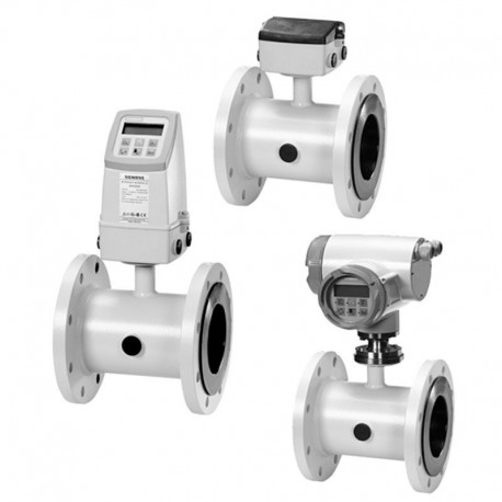 View larger
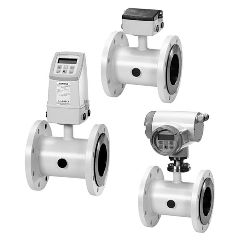
Sensor types MAG 5100 W
New product
Transmitter types MAG 5000, MAG 6000 and Transmitter types MAG 5000CT, MAG 6000CT
More info
Application
The main applications of the SITRANS F M electromagnetic flow
sensors can be found in the following fields:
• Water abstraction
• Water treatment
• Water distribution network (leak detection management)
• Custody transfer water meters
• Irrigation
• Waste water treatment
• Filtration plant (e.g. reverse osmosis and ultra filtration)
• Industrial water applications
Mode of operation
The flow measuring principle is based on Faradays law of electromagnetic induction according to which the sensor converts
the flow into an electrical voltage proportional to the velocity of the flow.
Integration
The complete flowmeter consists of a flow sensor and an associated transmitter SITRANS F M MAG 5000, MAG 6000 or
MAG 6000 I.
The flexible communication concept USM II simplifies integration and update to a variety of fieldbus systems, e.g. HART, DeviceNet,
PROFIBUS DP and PA, FOUNDATION Fieldbus H1, Modbus RTU/RS485.
The SITRANS F M MAG 5100 W is an electromagnetic flow sensor designed to meet ground water, drinking water, waste water,
sewage or sludge applications.
Benefits
DN 15 to DN 1200 / 2000 (1” to 48" / 78”)
• Stock program of MAG 5100 W secures short delivery time
• Connection flanges EN 1092-1 (DIN 2501), ANSI, AWWA, AS
and JIS.
• NBR Hard Rubber and Ebonite Hard Rubber liner for all water
applications
• EPDM liner with drinking water approvals
• Hastelloy integrated grounding and measuring electrodes
• Increased low flow accuracy for water leak detection, due to
coned liner design (Order No. 7ME6520, DN 15 to 300 mm
(1" to 12")).
• Drinking water approvals
• Suitable for direct burial and constant flooding
• Custody transfer approvals
• Build-in length according to ISO 13359
• Easy commissioning, SENSORPROM unit automatically uploads
calibration values and settings.
• Designed so patented in-situ verification can be conducted.
Using SENSORPROM fingerprint.
• Custody Transfer option for water billing, with type approval after
OIML R49 and verified according to MI-001 for DN 50 (2")
to DN 300 (12")
- Pattern approval OIML R 49 (Denmark, Germany)
- conforms to ISO 4064 and EN 14154
- MI-001 Custody Transfer approval for billing (EU)
• Meets EEC directives: PED, 97/23/EC pressure directive for
EN1092-1 flanges
• Simple onsite or factory upgrade to IP68/NEMA 6P of a standard
sensor
• MCERTS approval for UK environmental market
Installation, connection, commissioning, and service must be carried out by personnel
who are qualified and authorized to do so.
• It is very important that the same people have read and understood the instructions and
directions provided in this manual and that they follow the instructions and directions
before putting the equipment into use!
• People who are authorized and trained by the owner of the equipment may operate the
equipment.
• The installer must ensure that the measuring system is correctly connected and is in
accordance with the connection diagram. The transmitter has to be earthed by means
of a 4 mm2 potential equalising conductor.
• In applications where the operating pressure or media can be hazardous in the event
of a pipe failure, we recommend that special precautions are taken during the installation
of the sensor, such as sensor location, guarding or the use of a pressure relief valve.
• Siemens Flow Instruments can provide assistance with the selection of sensor parts in
contact with the media. However, the full responsibility for the selection rests with the
customer and Siemens Flow Instruments can take no responsibility for any failure due
to material incompatibility.
Equipment used in hazardous areas must be Ex-approved and marked .
It is required that the "Special Conditions for Safe Use" provided in the manual and in
the Ex certificate are followed!
• Installation of the equipment must comply with national regulations.
Example EN 60079-14 for the European Community.
• Repair and service can be done by approved Siemens Flow Instruments personnel only.
Manufacturer's design and safety statement
1. Responsibility for the choice of lining and electrode materials with regard to their abrasion
and corrosion resistance lies with the purchaser; the effect of any change in process medium
during the operating life of the flowmeter should be taken into account. Incorrect selection
of lining and/or electrode materials could lead to a failure of the flowmeter.
2. It is the responsibility of the user to ensure that stresses and loading caused by earthquakes,
traffic, high winds and fire damage are taken into account during installation, when
appropriate. These forces are not taken into account during flowmeter design.
3. It is the responsibility of the user to ensure that the flowmeter is installed such that it does not
act as a focus for pipeline stresses. External loading are not taken into account during
flowmeter design.
4. During operation do not exceed the pressure and/or temperature ratings indicated on the
data label or in the installation instructions.
5. It is the responsibility of the user to ensure that all installations include over pressure
protection, means for draining/venting, and that adequate protection is provided to minimize
any risk of contact with hot surfaces.
6. Under the Pressure Equipment Directive this product is a pressure accessory, and not
approved for use as a safety accessory, as defined by the Pressure Equipment Directive.
7. Removal of the terminal box except by Siemens Flow Instruments or their approved agents
will invalidate the PED conformity of the product.
In accordance with the Pressure Equipment Directive (97/23/EC)
Product introduction
Electromagnetic flowmeters are suitable for measuring the flow of almost all electrically
conducting liquids, pastes and slurries.
A prerequisite is that the medium must have a minimum conductivity of 5 µS/cm and a solid content
of maximum 40%. The temperature, pressure, density, and viscosity have no influence on the result.
The main applications of the electromagnetic flowmeters can be found in the following sectors:
• Water and wastewater
• Chemical and pharmaceutical industries
• Food and beverage industry
• Mining, aggregates and cements industries
• Pulp and paper industry
• Steel industry
• Power; utility and chilled water industry
The wide variety of combinations and versions from the modular system means that ideal
adaptation is possible to each measuring task.
SITRANS F M electromagnetic flowmeters are characterised by simplicity:
? Simple to install
? Simple to commission
? Simple to operate
? Simple to maintain
SITRANS F M electromagnetic flowmeters are manufactured by Siemens Flow Instruments A/S
- one of the world's leading manufacturers of flowmeters.
All SITRANS F M electromagnetic flowmeters feature a unique SENSORPROM® memory unit
which stores sensor calibration data and transmitter settings for the lifetime of the product.
At commissioning the flowmeter commences measurement without any initial programming.
The factory settings matching the sensor are stored in the SENSORPROM® unit. Also customer-
1.1
Product introduction
1. Product introduction
SITRANS F M electromagnetic flowmeters are characterised by simplicity:
? Simple to install
? Simple to commission
? Simple to operate
? Simple to maintain
SITRANS F M electromagnetic flowmeters are manufactured by Siemens Flow Instruments A/S
- one of the world's leading manufacturers of flowmeters. specified settings are downloaded to the
SENSORPROM® unit. Should the transmitter be replaced, the new transmitter will upload all
previous settings and resume measurement without any need for re-programming.
Furthermore, the "fingerprint" used in connection with the Siemens Flow Instruments Verificator is
stored during the sensor calibration.
USM II "Plug & Play" add-on communication modules.
USM II - the Universal Signal Module with "Plug & Play" simplicity makes it easy to access and integrate
the flow measurement with almost any system. It ensures the flowmeter will be easy to upgrade to new
communication platforms in the future, too.
Mode of operation
The flow measuring principle is based on Faraday’s law of electromagnetic induction.
Ui = When an electrical conductor of length L is moved at velocity v, perpendicular to the lines of
flux through a magnetic field of strength B, the voltage Ui is induced at the ends of the conductor
Ui = L x B x v
Ui = Induced voltage
L = Conductor length = Inner pipe diameter = k1
B = Magnetic field strength = k2
v = Velocity of conductor (media)
k = k1 x k2
Ui = k x v, the electrode signal is directly proportional to the fluid velocity
A flowmeter consists of a sensor (MAG 1100, MAG 1100 F, MAG 3100, MAG 3100 P or MAG 5100 W)
and a transmitter (MAG 5000 or 6000).
SENSOR
The sensor converts the flow into an electrical voltage (Ui) proportional to the velocity of the flow.
The sensor is built up of a stainless steel pipe, 2 coils, electrodes, an isolating liner, housing and,
where applicable, connecting flanges.
TRANSMITTER
The transmitter consists of a number of function blocks which convert the sensor voltage into flow
readings.
Power supply
Two different types of power supply are available. A 12 ... 24 V AC/DC and a 115 ... 230 V AC switch
mode type.
Coil current module generates a pulsating magnetizing current that drives the coils in the sensor.
The current is permanently monitored and corrected. Errors or cable faults are registered by the selfmonitoring
circuit.
Input circuit amplifies the flow proportional signal from the electrodes. The input impedance is
extremely high: >1014 ? which allows flow measurements on fluids with conductivities as low as
5 µS/cm. Measuring errors due to cable capacitance are eliminated due to active cable screening.
Digital signal processor converts the analog flow signal to a digital signal and suppresses
electrode noise through a digital filter. Inaccuracies in the transmitter as a result of long-term drift
and temperature drift are monitored and continuously compensated for via the self-monitoring
circuit. The analog to digital conversion takes place in an ultra low noise ASIC with 23 bit signal
resolution. This has eliminated the need for range switching. The dynamic range of the transmitter
is therefore unsurpassed with a turn down ratio of minimum 3000:1.
CAN communication
The transmitter operates internally via an internal CAN communication bus. Signals are transferred
through a signal conditioner to the display module, and to/from internal/external option modules
and the dialog module.
Dialog module
The display unit consists of a 3-line display and a 6-key keypad. The display shows a flow rate or
a totalizer value as primary reading.
Output module converts flow data to an analog, a digital and a relay output. The outputs are
galvanically isolated and can be individually set to suit a particular application.
Pressure Equipment Directive 97/23EC
Since 30 May 2002 the "Pressure Equipment Directive" is mandatory for all pressure equipment
sold within the EU and EFTA.
Siemens Flow Instruments products confirms to PED by following the tables below.
MAG 5100 W (7ME6580 only < DN600 (< 24"))
DN25 to DN2000
MAG 3100
DN15 to DN2000
MAG 3100 high temperature and 3100 P
DN15 to DN300
MAG 1100 and MAG 1100 F
DN2 to DN100
All products sold outside of EU and EFTA are excluded from the directive, also products sold into
certain market sectors are excluded. These include
1) Meters used in networks for the supply, distribution and discharge of water.
2) Meters used in pipelines for the conveyance of any fluid from offshore to onshore.
3) Meters used in the extraction of petroleum or gas, including christmas tree and manifold
equipment.
4) Any meter mounted on a ship or mobile offshore platform.
Product marking example
All meters will now carry either a CE mark or a CE mark followed by for example 0086
CE0086: This indicates that the product conforms to PED 97/23/EC, LVD 2006/95/EC, &
EMC 2004/108/EC
CE: This indicates that the product conforms to LVD 2006/95/EC & EMC 2004/108/EC
Sensor MAG 1100 and MAG 1100 HT (High temperature)
Sensor MAG 1100 F
Sensor MAG 3100, MAG 3100 HT and MAG 3100 P
Sensor MAG 5100 W
Custody Transfer (only together with MAG 5000/6000 CT)
Certificates
OIML R 49 pattern approval cold water (Denmark
and Germany): DN 50 ... 300 (2" ... 12")
(For further details see approval :
08-3412 TS 22.36 005 or PTB 6.221/05.21)
MI 001 cold water (EU): DN 50 ... 300 (2" ... 12")
Transmitter MAG 5000 / MAG 6000
Electromagnetic with pulsed constant field
Detection of empty pipe (special cable required in remote mounted installation)
Depends on sensor size
For detection of empty sensor the min. conductivity must always be >50 µS/cm and the max. length
of the electrode cable when remote mounted is 50 meters (164 ft). Special cable must be used!
For 19" Ex applications with safety barriers special cable cannot be used and the empty pipe
function can therefore not be used. For these applications 25 meters (82 ft) of cable can be used
in order to obtain 0.25% and 50 meters (164 ft) to obtain 0.5%.
For remote MID installations the max. cable length is 3 meters (9.8 ft). For other CT application
standard requirements are applicable.
Empty sensor detection is not available with DN 2, 3 (1/12, 1/8 inch) sizes.
Guidelines for selection of sensor
Min. measuring range: 0 ... 0.25 m/s
Max. measuring range: 0 ... 10 m/s
Normally the sensor size is selected so that the nominal flow velocity v lies within the measuring
range 1 ... 3 m/s.
Guidelines for selection of sensor
Min. measuring range: (0 ... 0.8 ft./sec)
Max. measuring range: (0 ... 33 ft./sec)
Normally the sensor size is selected so that the nominal flow velocity v lies within the measuring
range (1 ... 15 ft./sec.)
Installation conditions
Transmitter can be mounted compact or remote.
The sensor must always be completely full with liquid.
(For further details see approval : DK-0200-MI001-001)
Therefore avoid:
• Installation at the highest point in the pipe system
• Installation in vertical pipes with free outlet
For partially filled pipes or pipes with downward flow and free outlet the flowmeter should be
located in a U-tube.
Recommended flow direction: upwards. This minimizes the effect on the measurement of
any gas/air bubbles in the liquid.
The sensor must be mounted as shown in the upper figure. Do not mount the sensor as shown
in the lower figure. This will position the electrodes at the top where there is possibility
for air bubbles and at the bottom where there is possibility for mud, sludge, sand etc.
If using empty pipe detection, the sensor can be tilted 45°, as shown in the upper figure.
Measuring abrasive liquids and liquids containing particles
Recommended installation is in a vertical/inclined pipe to minimize the wear and deposits in
the sensor.
Inlet and outlet conditions
To achieve accurate flow measurement it is essential to have straight lengths of inlet and
outlet pipes and a certain distance between pumps and valves.
It is also important to centre the flowmeter in relation to pipe flanges and gaskets.
Potential equalization
The electrical potential of the liquid must always be equal to the electrical potential of the sensor.
This can be achieved in different ways depending on the application:
A. Wire jumper between sensor and adjacent
flanges. (MAG 1100 and MAG 3100).
B. Direct metallic contact between sensor and
fittings. (MAG 1100 FOOD).
C. Built-in grounding electrodes. (MAG 3100
and MAG 5100 W).
D. Optional earthing/protection flanges/rings.
(MAG 1100 and MAG 3100).
E. Optional graphite gaskets on MAG 1100.
(Standard for MAG 1100 High temperature).
Vacuum
The flowmeter can be installed between two reducers (e.g. DIN 28545). At 8° the following
pressure drop curves apply. The curves are applicable to water.
Compact/remote installation
Max. ambient temperature as a function of temperature of medium.
The transmitter can be installed either compact or remote.
With compact installation the medium temperature must be in accordance with the graph.
With remote installation, the cable length and type described under "Technical data", chapter
2 must be used.
IP 68 applications only
If the sensor is buried or permanently submerged, the terminal box must be encapsulated
with silicon dielectric gel.
Mix the two components well and pour the contents into the terminal box.
The material is a non-toxic, transparent, selfhealing gel which cures in approx. 24 hours at
approx. 25°C (77°F) (curing time will increase by 100% per -10 °C).
The gel can be penetrated with test instruments or be removed in case of cable replacement.
The potting kit cannot be used for ATEX applications.
Suggestions for the direct burial of MAG 3100 & MAG 5100 W sensors
If MAG 3100 or MAG 5100 W sensors are buried directly into the ground, the SENSORPROM®
unit should be removed from the terminal box on the sensor and relocated in the remote
transmitter prior to burying the sensor.
AC-cleaning
AC-cleaning is used to remove fatty deposits on the electrodes. These fatty deposits are seen in
wastewater applications, in abbatoirs and water applications with oil residuals. During the cleaning
process, the surface of the electrodes get warmer, which tends to soften grease particles and the
gas bubbles generated mechanically lift deposits away from the surface of the electrodes.
DC-cleaning
DC-cleaning is used to eliminate electrically conductive deposits in the measuring pipe influencing
the measuring accuracy.
Particularly in district heating applications an electrically conductive deposit (magnetite) may occur
and short-circuit the electrode signal. In this case the accuracy of the meter decreases and the
signal/noise conditions of the meter become inferior. The problem only arises if the conductivity of
the water is less than approx. 250 µS/cm.
During DC-cleaning, electrolysis takes place where the flow of electrons removes the particle
deposits from the electrode area.
Custody transfer approval
A transmitter can be supplied in a version tested and approved for custody transfer (CT). The
internal counter can accordingly be used for charging.
This requires verification, sealing and setting of the transmitter together with the sensor for a
specific flow range. After sealing the data on the transmitter must not be changed.
The sealing of the transmitter is done by placing sealing marks on the transmitter and on the
connection plate in the terminal box.
P indicates sealing locations
Transmitter MAG 5000 CT, MAG 6000 CT
Sealing
MAG 6000 CT is installed like a standard MAG 6000 except for the final sealing.
Calibration sealing has been carried out at calibration.
Approvals
SITRANS F M sensors are ATEX approved according to the following approvals
MAG 1100, MAG 1100 F for mounting in Ex areas SIRA 07 ATEX 3181X
MAG 3100, MAG 3100 P for mounting in Ex areas SIRA 03 ATEX 3339X
MAG 6000 & safety barriers carry the following approvals
For use with MAG 1100, MAG 1100 F, MAG 3100 and MAG 3100 P for mounting in the safe area
[EEx ia ib] IIB, II 2 G DEMKO 03 ATEX 135255X CE539
Potential equalization
To obtain optimum results from the measuring system, the chassis body of the sensor must have
the same electrical potential as the liquid being measured.
MAG 1100 F
The sensor must be installed between two adapters.
Potential equalization with the liquid occurs automatically via these adapters and
through the adjacent pipe.
MAG 3100 / MAG 5100 W (except PTFE and PFA liner)
Potential equalization is carried out with the built-in grounding electrodes. No further actions
need to be taken.
Please note: MAG 3100 has no grounding electrodes if the electrodes materials are
platinium or tantalum or PN 100.
Installation of sensor
MAG 3100 (PTFE liner and PFA)
Electrically conductive piping Use an earth strap on one side.
Non-conductive piping
Use an earthing flange. Place the flange between flowmeter and the adjacent pipe flange.
Selection of earthing flange depends on the medium, liner material and application.
Inlet protection MAG 3100
With abrasive liquids, flowmeter inlet protection may be necessary. Here type C and E earthing
flanges are used.
Type C (for all liners except PTFE and PFA) is clamped between the flanges.
Type E (for PTFE liner only) is fitted to the flange.
Flat ring (for PFA liner only) is fitted to the flange.
When using an earthing flange, gaskets must always be used between the adjacent pipe
flange and the earthing flange.
Cathodic protected piping
Special attention must be given to systems with cathodic protection.
Compact installation:
The transmitter must be supplied through an isolation transformer. The terminal "PE" must
never be connected.
Remote installation:
The screen must only be connected at the sensor end via a 1.5 µF condensator. The
screen must never be connected at both ends.
Isolated sensor:
If above mentioned connections are unacceptable, the sensor must be isolated from the pipe work.
The bolts must be isolated from pipe.
Installation of transmitter
Compact installation MAG 5000 and MAG 6000
Compact polyamide
Step 1
Remove and discard the terminal box lid of the
sensor.
Fit the M20/1NPT cable glands for the supply
and output cables.
Step 2
Remove the two black plug assemblies for coil
and electrode cables in the terminal box and
connect them to their corresponding terminal
numbers on the connection board.
Step 3
Connect earth wire on connection board to
bottom of connection box.
Connect the 2 pin connector and 3 pin connector
as shown.
Note
In earlier version the 3 pin connector was a 5 pin
connector.
Step 4
Mount the connection plate in the terminal box.
The SENSORPROM® unit connections will be
established automatically when the connection
plate is mounted in the terminal box.
Note
Check that your connection board lines up with
the SENSORPROM® unit, if not, move the
SENSORPROM® unit to the other side of the
terminal box.
Step 5
Fit the supply and output cables respectively
and tighten the cable glands to obtain optimum
sealing.
Please refer to the wiring diagram in chapter 7
for the electrical connections.
Mount the transmitter on the terminal box.
Turning the control pad
1. Use a screwdriver to remove the outer
frame.
2. Loosen the 4 screws retaining the control
pad.
3. Withdraw the control pad and turn it to the
required orientation.
4. Tighten the 4 screws until a mechanical
stop is felt in order to obtain IP 67 enclosure
rating.
5. Snap-lock the outer frame onto the control
pad (click).
Turning the transmitter
The transmitter can be mounted in either direction as the arrow indicates without turning
the terminal box.
The connection board needs to be oriented according to the display direction.
The terminal box can be rotated ±90° in order
to optimize the viewing angle of the transmitter display/keypad:
1. Unscrew the four screws in bottom of terminal box.
2. Turn terminal box to required position.
3. Retighten screws firmly
Add-on modules MAG 6000 only
Locate the add-on module in the bottom of the MAG 6000 transmitter.
Press the add-on module forwards as far as possible.
The add-on module has now been installed and the transmitter is ready to be installed on
the terminal box.
Communication to the operator menu and electrically inputs and outputs is automatically
established by power on.
Remote installation - At the sensor
Step 1
Remove the terminal box lid of the sensor.
Step 2
Remove the SENSORPROM® unit from the sensor and mount it on the connection plate in
the transmitter.
Step 3
Fit the 1”NPT or M20 cable glands for the supply and output cables.
Fit and connect the electrode and coil cables as shown in chapter 7 “Electrical connections”.
The unscreened cable ends must be kept as short as possible.
The electrode cable and the coil cable must be kept separate to prevent interference.
Tighten the cable glands well to obtain optimum sealing.
Step 4
Mount the lid on the terminal box.
Mount wall bracket on a wall or into the back of a panel.
Mount wall bracket on a vertical or horizontal pipe using an ordinary hose clip or a duct strap.
Remote installation - Wall mounting
Step 2
Take the SENSORPROM® memory unit from the sensor. Mount the SENSORPROM® unit in
the wall mounting unit as shown. The text on the SENSORPROM® unit must face towards the wall bracket.
Mount an earth wire between PE on connection board and bottom of connection box.
PS.027.W6.02
6. Installation of transmitter
Installation of transmitter
Step 2
Take the SENSORPROM® memory unit from
the sensor. Mount the SENSORPROM® unit in
the wall mounting unit as shown. The text on the
SENSORPROM® unit must face towards the
wall bracket.
Mount an earth wire between PE on connection
board and bottom of connection box.
6.2.3
Remote installation -
Wall mounting
(continued)
MAG 6000
Step 3
Mount the connection plate in the terminal box.
Fix the connection plate with the two diagonal opposite screws.
Fit the coil B , electrode A , supply C and output cables D respectively and tighten the cable
glands to obtain optimum sealing. Please see the wiring diagram in “Electrical connections”.
Step 4
Mount the transmitter on the terminal box.
Remote installation - Transmitter in 19" insert
1. Fit the SENSORPROM® memory unit on the connection board supplied with the transmitter.
The SENSORPROM® unit is supplied with the sensor in the terminal box.
2. Mount the guide rails into the rack system as shown. Distance between guide rails is 20 TE.
Guide rails are supplied with the rack system and not with the transmitter.
3. Mount the connection board as shown.
4. Connect the cables as shown under "Electrical connection", chapter 7.
5. Insert the transmitter into the rack system.
Remote installation
Sensor cables
• Unscreened cable ends must be as short as possible and the two cables must be kept separate.
Cables must be in one length and must not be taken to a distribution box or similar terminal
arrangement.
• Terminals 81 and 84 are only connected when special electrode cable with double screening
is used.
• Coil cable screen must be connected in both ends. Electrode cable screen must be connected
at sensor side only.
Note
See 5.3 when using cathodic protection
Menu build-up
The menu structure of a specific transmitter type is shown in a menu overview map.
Details of how a specific parameter is set is shown in a menu detail map for the specific parameter.
A detail map is valid for each type of transmitter if not indicated otherwise. The menu structure is
valid for the title and subtitle line only. The upper line is for primary readings only and will always
be active with either flowrate, totalizer 1 or totalizer 2.
The menu is built up in two parts. An operator menu and a setup menu.
Setup menu
The setup menu is for commissioning and service only.
Access to the setup menu is gained by pressing the top up key for 2 seconds. The setup menu
operates in two modes:
• View mode
• Setup mode
View mode is a read only mode. The pre-selected settings can only be scanned.
Setup mode is a read and write mode. The pre-selected settings can be scanned and changed.
Access to the setup mode is password-protected. The factory set password is 1000.
Access to a submenu in the set up menu is gained by the lock key. A short press on the top up key
will bring you back to the previous menu. A long press (2 sec.) on the top up key will exit the
setup menu and bring you back to operator menu No. 1.
Access to change mode is password protected. The password is factory set to 1000, but can be changed to any value between 1000 and 9999 in the change password menu.
The factory setting of 1000 can be re-established as follows:
• Switch off power supply
• Press the top up key and switch on the power supply
• Release the key when the transmitter is started up again
The user code is now reset to 1000.